User Interface
TracePro sets itself apart from other optical and illumination design software solutions with its uniquely friendly and intuitive graphical user interface. Mechanical engineers and others familiar with CAD software will experience the shortest learning curve with TracePro.
TracePro is a standard Windows application that uses a menu bar, icon-based toolbars, drop-down menus, and a system tree. The working area, called the Model View, is where users will add and manipulate models they want to simulate and optimize. Properties, utilities, and other features appear in windows, drop-down menus, dialog boxes, property sheets, etc.
In the Model View and with certain utilities, you can move objects and modify control points and segments into place using the drag-and-drop interface. Rotate, scale, and orientation can also be manipulated in the Model View or by using commands in the menu bar.
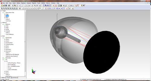
Elliptical reflector example is shown in rendered view with transparency and a few rays visualized
- Rendered
- Silhouette
- Wireframe Hidden Line
Measurement tools
Measure distance from:
- Vertex to vertex
- Vertex to edge
- Vertex to surface
- Edge to edge
- Edge to surface
- Surface to surface
Creating geometries within TracePro is extremely simple. You can add primitive solids, such as blocks, cylinders, cones, tori, spheres, and thin sheets. Boolean operations enable you to intersect, subtract, and unite overlapping primitive bodies to create more complex models. Almost any surface can be extruded or revolved any number of times to create complex light pipes, lenses or reflector shapes. TracePro also allows you to create lenses, Fresnel lenses, reflectors, tubes, and baffle vanes.